|
This version is based on an Arduino chip. I laid out a circuit boatrd
for it and orderd them. This is a description of how they work and some
assembly tips.
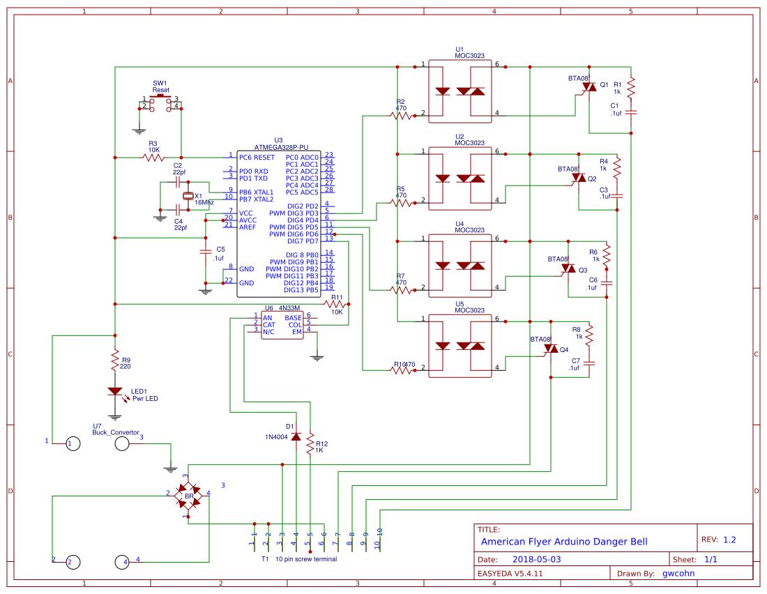

The control board is designed to work with a standard AC powered American Flyer train layout. For more realistic effect, the 759 and 761 Danger lights need to be modified as shown above to allow each lamp to be controlled individually. The circuit description is a s follows: Power from the 16 volts of the train transformer is rectified by a bridge rectifier where it becomes about 22 volts DC. It is fed to the buck convertor module which is adjusted to provide 5 volts DC for the ATmega 328 processor chip. The processor chip is triggered into running it's program when pin 13 is pulled low. U8 which is an opto isolater consists of a LED and photo transistor embedded in a plastic chip. When the LED is powered, the transistor turns on and pulls the processor input pin low. The resistor and diode connected to the opto isolator rectifies the AC from the 696 track trip and drops the voltage to a level that will not damage the LED. The diode protects the opto isolater LED from excessive reverse voltages. Once the program is triggered, outputs from the ATmega processor turn on the LED's in a sequence in U1, U2, U4, and U5. These are actually triacs that are triggered by LED, very similar to the optoisolater desribed above. These in turn trigger the larger triacs which switch the 16 volts AC on and off for the lights, bell, and crossing gate. The resistor and capacitor across each triac provides a "snubber" network. When driving inductive loads such as the coil in the bell and crossing gates, they may generate a spike of voltage when turned off and the snubber networks keep that from retriggering the triac before intended. The reason for the opto isolors was to isolate the 16 volts AC from the processor as it would destroy the chip immediately. The circuit is a bit of over kill but the parts are extremely cheap from many of the vendors on eBay. For example, the buck convertor module is about $1.45 which is cheaper than trying to use a linear regulator like an LM7805 and it's associated support components. A short YouTube video showing an early prototype board in operation can be seen HERE. The revised board can be seen in This video. Some notes on hooking it up are HERE. |