 |
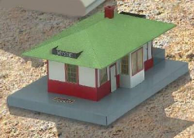
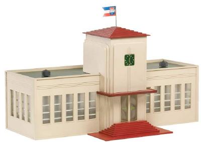
This was my attempt to improve upon the operation of the various talking stations such as the Mystic and Union Stations. The goal was to provide an electronic way of generating the various statiom messages and controlling the train at the same time, synchronized with the playing of the message. Playing of the original records more than a few times literally carves the grooves away so I wanted to be able to record the sound to a digital chip and play it back from there, preserving the original records and mechanisms. It also gives me the opportunity to use other recordings as well such as the NOMA station recordings. |
|---|

|
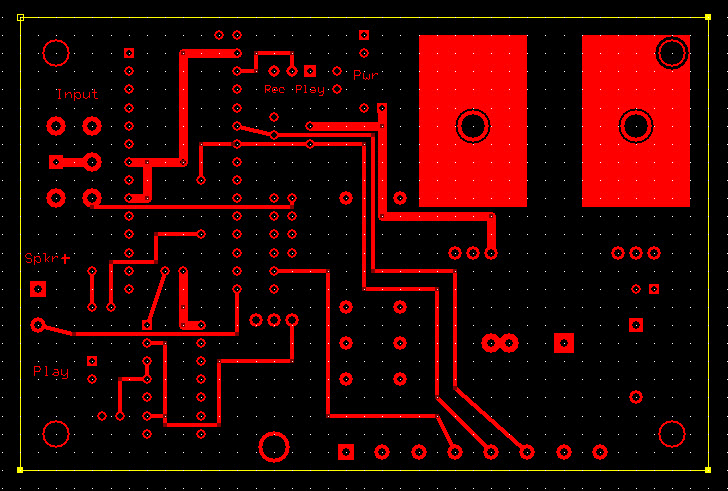
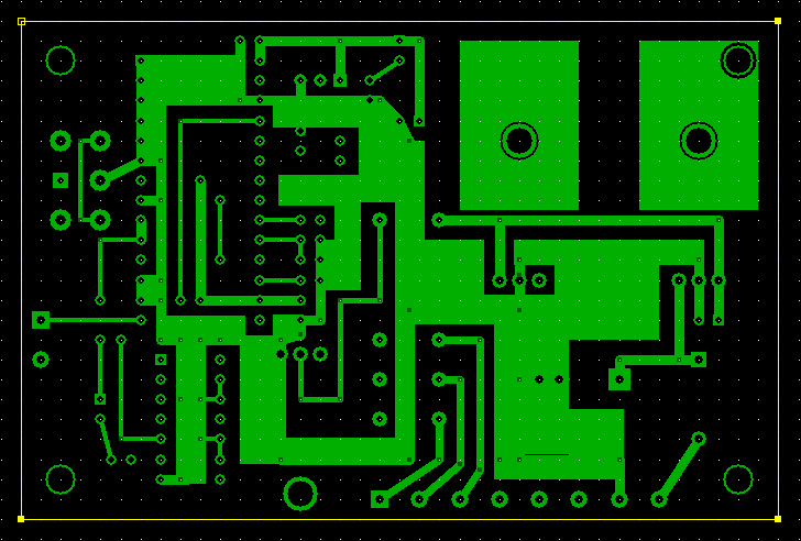
I haven't posted the shematic but I am working on it. Keep in mind that Winbond has discontinued the ISD 2500 series of sound chips but I had a bunch on hand so I decided to use them. Here are some images of a 2 layer pc board that I designed. Actual size of board is 2.8 inches high by 3.5 inches wide. My cost to get a board made runs about $20 per board for a minimum quantity of 3. These are drilled with plated through holes of commercial quality. To get the board with the silkscreen printed on it and solder mask around all of the solder pads would be about $28 per board in a minimum quantity of 3. The cost doesn't get reasonable until you are looking at hundreds of identical boards. For a quantity of 100 boards, the quoted cost per board finally drops to $4.78 each |
This was the original prototype. I have since built a better version based on the atmega328 processor, an LCD screen and a small mp3 sound card. It allows me to selct up to 10 different recordings. I will post that once I take some photos.
Here's a couple of videos of the prototype.
The one on the left shows that there are two different messages from the Colber recordings and the one on the right demonstrates the NOMA Diesel Streamliner recording.
The chip actually hold about 75 seconds worth of recordings so if you edit your sound files, It will play a different recording each time you press the start button.
The Stop/Reset button was just used in experimenting with it and is not needed in an operating situation.
Note the red LED that comes on when a recording is playing. This also indicates that the relay is on which would stop the train in the isolated section of the track. I'll have to put another video up showing that in action.
The speaker is a three inch 16 ohm speaker sitting in a plastic drinking glass just off to the left. I need to experiment with a little baffle box for it to get beter quality sound.
Here's a Bill of Materials:
The actual circuit for using the ChipCorder chip is fairly straightforward. I added a header with a little jumper on it so I could record audio from my computer into the chip, then move the jumper and it would play back every time I pushed the Start button. It's the yellow box with the Rec / Play below it on the Silkscreen view of the board.. At the same time, the 7400 NAND gate is configured as a latch and turns on the TIP 120 transistor which turns on the 12 volt relay which allows me to remove power from the isolated section of the track while the message is playing. Once the message ends, a low from the End-of-Message pin on the ChipCorder flips the latch, the relay turns off and the train moves out. An external 10 watt 10 ohm resistor will need to be used across the isolated section to keep the E unit from cycling when the relay removes power..I didn't have room to add it to the printed circuit board. |